Hello Folks,
Let’s start with one of my core interesting subject i.e. IoT (Internet Of Things). Today I’m going to focused on how to start, what needs to get start with basics of IoT and hands-on “Hello World” example.
The Pre-requisite for this and next few articles are:
1. Raspberry Pi or Arduino Board – in simple words it a small size computer that can connect to TV, Bluetooth, WiFi etc.
2. LEDs – required to check or test output ( visualize )
3. Jumper Cables – to connect the circuits and LED etc
Apart from above-
Download and Install Arduino editor
In this example I have used Arduino Uno board ( as it much cheaper than Raspberry Pi and more than enough for next few examples).
The board has GND, Analog and Digital and Power Pins. The board schematics can be found here
Lets have a look at our first example. In this we going to blink 2 LED one after another.
Open the editor can copy following code and save it as sketch_hello
void setup() {
  // put your setup code here, to run once:
  pinMode(4,OUTPUT);
  pinMode(7,OUTPUT);
}

void loop() {
  // put your main code here, to run repeatedly:
digitalWrite(4,HIGH);
delay(2000);
digitalWrite(7,HIGH);
digitalWrite(4,LOW);
delay(2000);
digitalWrite(7,LOW);
}
As you can see setup() and loop() are two building block/functions to start with.
The setup() method execute once in program lifetime and loop() runs through out. Usually setup() method we initialize/registered the Input, Output pins and other variables.
and in loop() method the main business logic.
Here in example I connected two LED to digital pins 4 and 7 and in loop() function and making them On and Off using HIGH and LOW. delay() functions used to introduced temporary delay/halt in program execution.
See the below picture showing how circuit looks after connection have been made
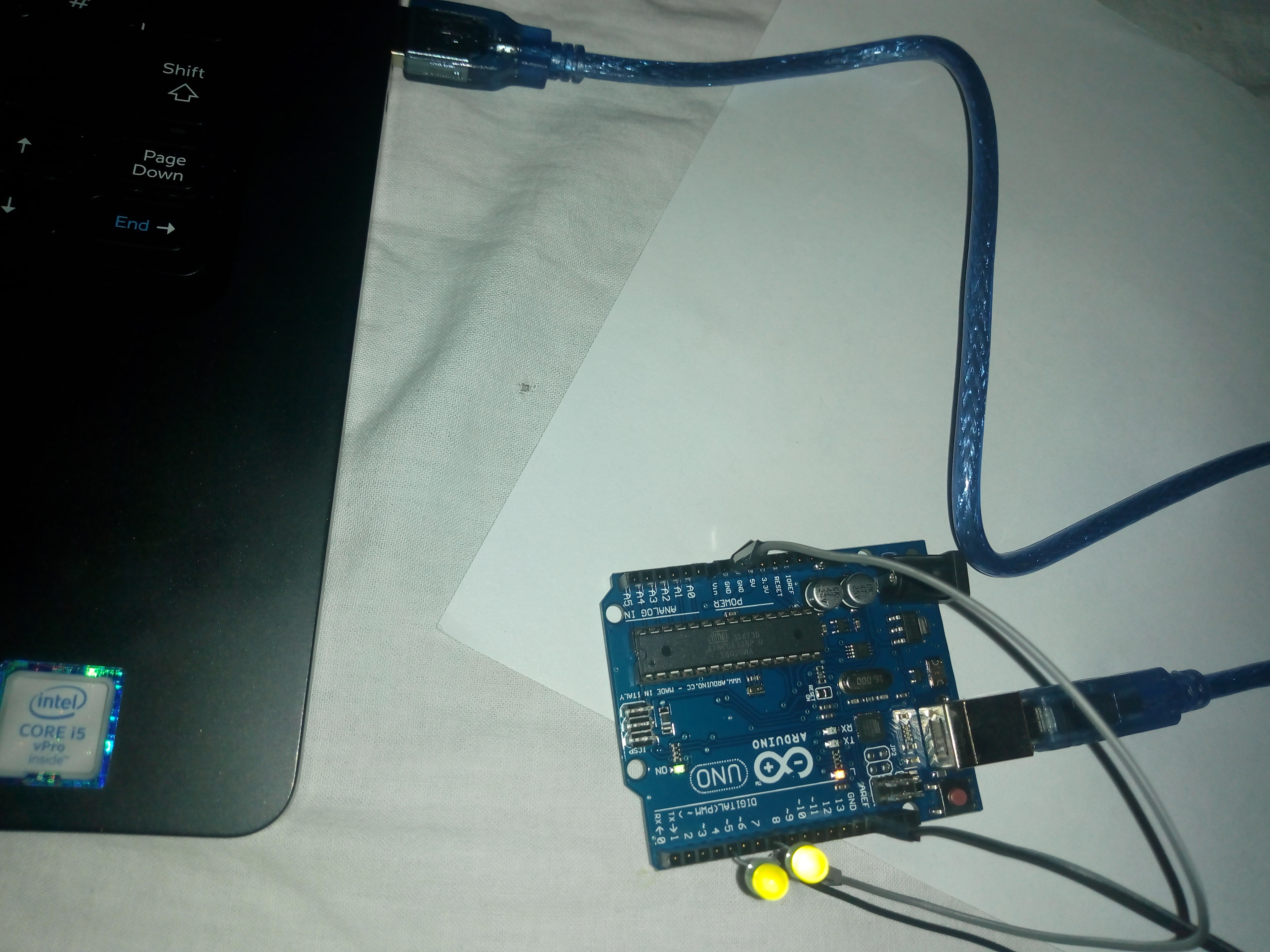
Circuit Connections
Attached 1st LED to jumper cable ( at Female-end) and connect Male-end of cable to one of GND on board. Connect LED to digital pin 4 (its one of output).
Simillarly, attached 2nd LED to jumper cable ( at female-end) and connect male-end of cable to another GND. Connect LED to digital pin 7 as another output.
Hurray Its time to test now – Once done Connect the board to laptop using power USB cable as shown in picture. Then click on ‘verify‘ button to compile the code.
Once compilation successful, click on ‘Upload‘ button to run program on actual board. Once uploading is done, you can see the LED start blinking one after another.
Bingo, you done it !!! Stay Connected.
